Transformers
ABB claims that only small frequency converters (FC) can be connected to an LV network without a transformer due to harmonics and EMC requirements. The different FC types are quite diverse in the amount of produced harmonics and so are the networks in their sensitivity. The decision whether to use an individual supply transformer or not must be made case by case.
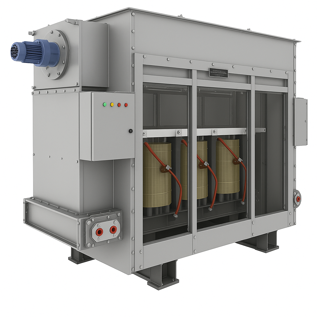 Fig.1. Transformer
example.
Fig.1. Transformer
example.
The supply transformer placed between the grid and the FC covers several different tasks:
- Galvanic isolation between the frequency converter and the feeding network.
- Voltage reduction from the feeding MV or HV network to the FC input level.
- Suppression of harmonics generated by the frequency converter, thus protecting the feeding network from harmonic contamination.
- Protection of ambient and the feeding network against radio-frequency interference produced by the rapidly commutating semiconductors.
Harmonic frequencies increase the mechanical and dielectric stresses and therefore the supply transformers must be specially designed for this duty.
Power, voltages and transformation ratio
Rated power
For transformer ratings under 10 MVA, IEC 60076-1 suggest preferred values based on the R10 series: 10, 12.5, 16, 20, 25, 31.5, 40, 50, 63, 80, 100, and multiples of 10n. For example, the preferred transformer sizes from 500 kVA to 4000 kVA are: 500, 630, 800, 1000, 1250, 1600, 2000, 2500, 3150, 4000.
Voltages at higher voltage (HV) side and lower voltage (LV) side
ABB claims that the VSD supply transformer is usually fed by a medium voltage network, but sometimes the transformer primary voltage may be at the LV level. Feeding from an HV network is also possible but rare. The input voltages in MV drives are from 1 kV to 36 kV. The input voltages in LV drives are usually between 380 V and 900 V, depending on the drive type".
In DriveConstructor it is possible to choose not exact values but ranges of values.
Voltage (HV)
The ranges can be chosen from the following: 2200-2500, 2500-2800, 2800-3200, 3200-3400, 3400-4100, 4100-4300, 4300-5800, 5800-6800, 6800-9000, 9000-12000 V. Choose range which fits grid voltage. Default setting is "any".
Voltage (LV)
The ranges can be chosen from the following: 380-440, 650-700, 2400-2500, 2900-3100, 3200-3400, 4100-4200, 5900-6700 V. Choose range which fits FC voltage. Default setting is "any".
Transformation ratio
In DriveConstructor the ratio is defined by the ranges chosen for the grid side (MaxHV-MinHV) and FC side (MaxLV-MinLV) and the additional adjustments made manually (see the software). The range of ratios is:
- minimum ratio is calculated as MaxHV/MinLV,
- maximum ratio is calculated as MinHV/MaxLV.
Then the ratio can be "manually" adjusted within the range between minimum and maximum values.
Types of transformers
Dry or liquid-filled
Basically, there are two distinct types of transformers: Liquid insulated and cooled (liquid-filled type) and non-liquid insulated, air or air/gas cooled (dry type) - see Fig. 2 and 3. Also, there are subcategories of each main type.
Liquid-filled transformers (also called oil-immersed) are normally more efficient than dry-types, and they usually have a longer life expectancy. Also, liquid is a more efficient cooling medium in reducing hot spot temperatures in the coils. In addition, liquid-filled units have a better overload capability. There are some drawbacks, however. For example, fire prevention is more important with liquid-type units because of the use of a liquid cooling medium that may catch fire. (Dry-type transformers can catch fire, too.) It's even possible for an improperly protected wet-type transformer to explode. And, depending on the application, liquid-filled transformers may require a containment trough for protection against possible leaks of the fluid.
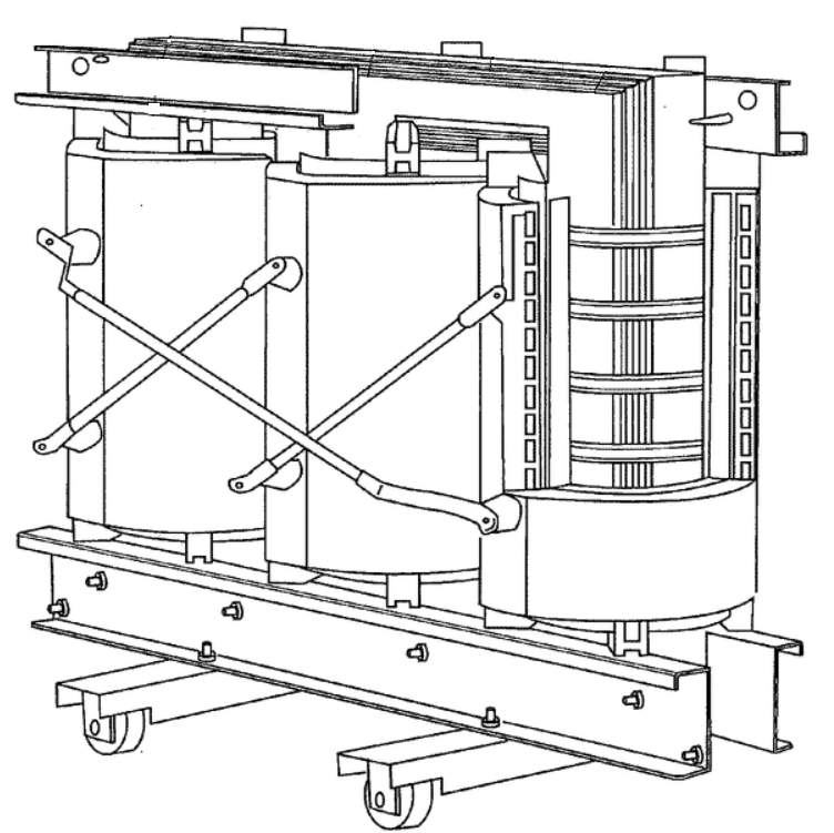 Fig.2. Dry
transformer (without enclosure).
Fig.2. Dry
transformer (without enclosure).
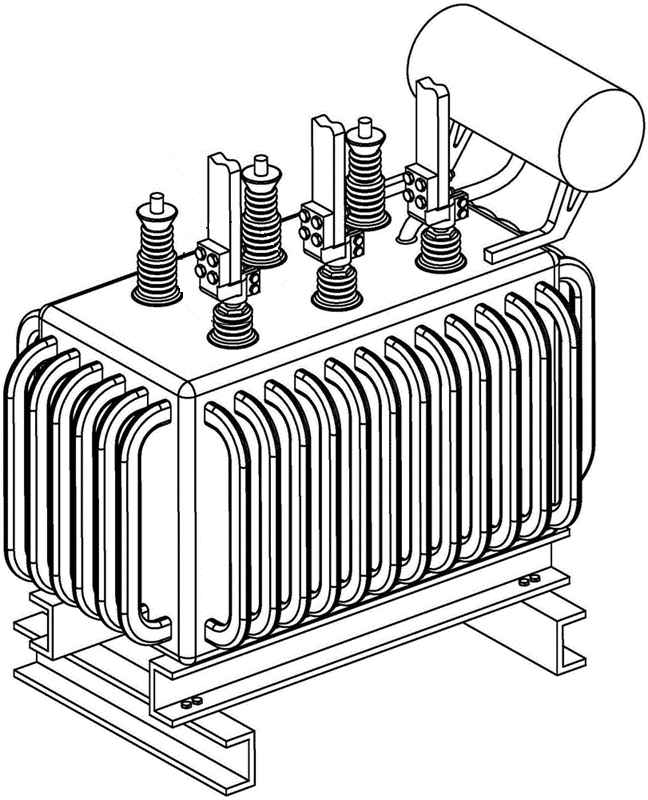 Fig.3. Oil-filled
transformer.
Fig.3. Oil-filled
transformer.
Arguably, when choosing transformers, the changeover point between dry-types and wet-types is between 500 kVA to about 2.5 MVA, with dry-types used for the lower ratings and wet-types for the higher ratings.
Important factors when choosing what type to use include where the transformer will be installed, such as inside an office building or outside, servicing an industrial load.
Dry-type transformers with ratings exceeding 5 MVA are available, but the vast majority of the higher-capacity transformers are liquid-filled. For outdoor applications, wet-type transformers are the predominate choice.
Windings
Ordinary transformers have two windings; one primary and one secondary. However, there exist three- or four-winding transformers. ABB says: "The rectifiers used in low voltage VSDs are usually both 6-pulse or 12-pulse rectifiers, and they may be diode bridges, thyristor bridges or power transistor solutions. The 6-pulse rectifier is supplied by a two-winding transformer and the 12-pulse rectifier needs a three-winding transformer, having two separate secondary windings with 30 phase shift."
Special converters requiring multiple inputs call for multi-winding transformers.
In DriveConstructor there are the following options: "2-winding", "3-winding", "multi-winding".
Cooling type
Where the dissipation of heat is an important factor, the possibility to cool the electrical apparatus with water allows better management with the cooling system.
Integrated or stand-alone
Transformer can be integrated with the frequency converter or be mechanically separated, the latter variant called "stand-alone". Integrated designs are not common. Integration means usually sharing cooling system (heat exchanger, cooling ducts, water piping).
More information can be found here.